Why Weigh a Mouse?
Why weigh a mouse… well to catch it of course! Over the course of time, I have caught many mice from my gym and released them miles away. My gym recently moved to another location, where I did not think we would see many live mice because of all the poison kill traps outside the building, but I was wrong. The above picture is proof… Though we do see more dead mice here because I am told that the poison makes them thirsty and they search for water. If you are thinking that my gym must attract mice for some unsanitary reason you would definitely be wrong. Basically, my gym contains a garage door which has large gaps easily entered by mice. Not to mention that mice are curious creatures and seek out safe places from predators as well as any potential crumbs or water.
Anyway, getting back to the purpose of weighing a mouse to catch a mouse, in my previous mouse traps I had used a laser or led in conjunction with a photo-resistor as my “trip-wire”, but my next iteration will use this scale as my new “trip-wire”.
The goal of this post is to create a quick but meaningful log of a small step in my journey of making things.
In the longer term, I hope to make this the first of several laboratory “Log Book” entries that document my journey, aid me in the learning process, and help me in future creations for work and teaching.
From what I can pull from the internet it looks like a mouse is born at a weight of 1 to 2 grams and house mouse can be 40g to 45g (wiki). Jackson Lab mice go from 10 to 26.9g ±3.4g for female mice and 10 to 36.3±3.4g for male mice from age 3 to 24 weeks.
Therefore, a scale that can measure from 1 to 100 grams will work well as a trip-wire for my trap.
I obtained a 100g load cell configured as a single ended shear beam for 10$ (uxcell 100g Weighing Electronic Balance Wired Load Cell).
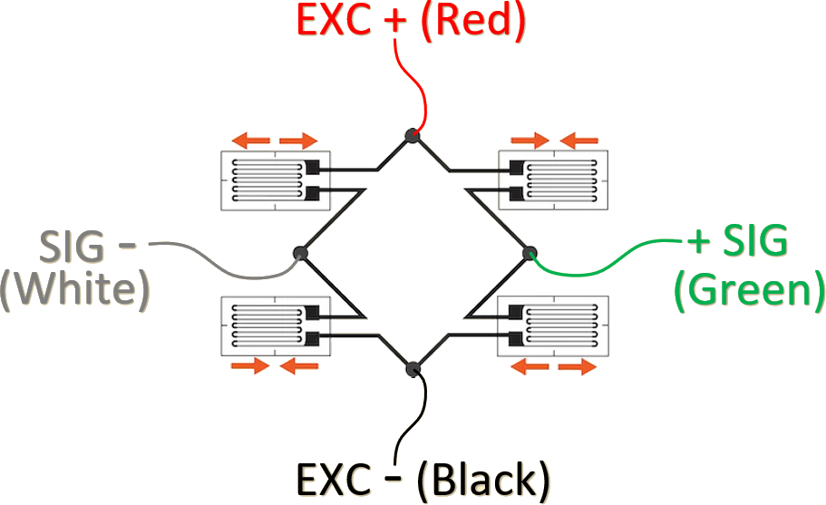
This is a single point load cell with a “dog bone” sensing section. This means, there are 4 strain gauges placed at the top and bottom of then end of the dog bone. These strain gauges are wired in a wheatstone bridge configuration .
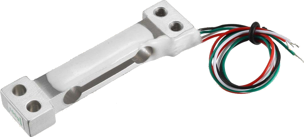
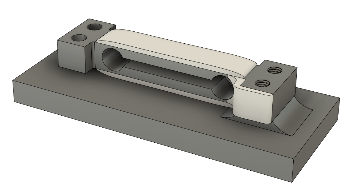
The load cell is anodized aluminum and the strain gauges are covered by a silica gel to protect against corrosion. Two of the holes are for mounting and are M3 in size. The other two holes are meant for a non-fixed or “floating” connection which I take to mean a “snug” fit.
The wires Red(EXC+), Black(EXC-) ,Green(SEN+), White(SEN-) are wired as shown in the schematic. The Sensitivity of the measurement is 0.7 ± 0.15 (mV/V) with error: ± 0.05 Full Scale (F.S.)
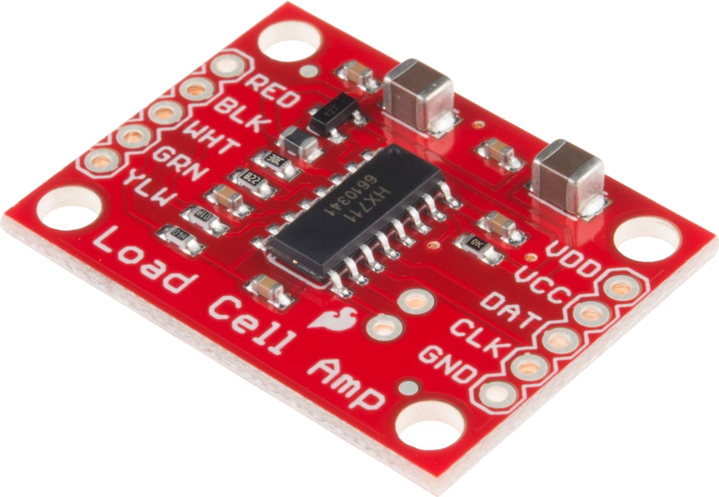
For 11$ I purchased a Load Cell Amplifier (HX711 Small Breakout Board).
The purpose of this amplifier is digitize the analog value from a load cell in the millivolt(mV) range of ±20mV or ±40mV (see datasheet)

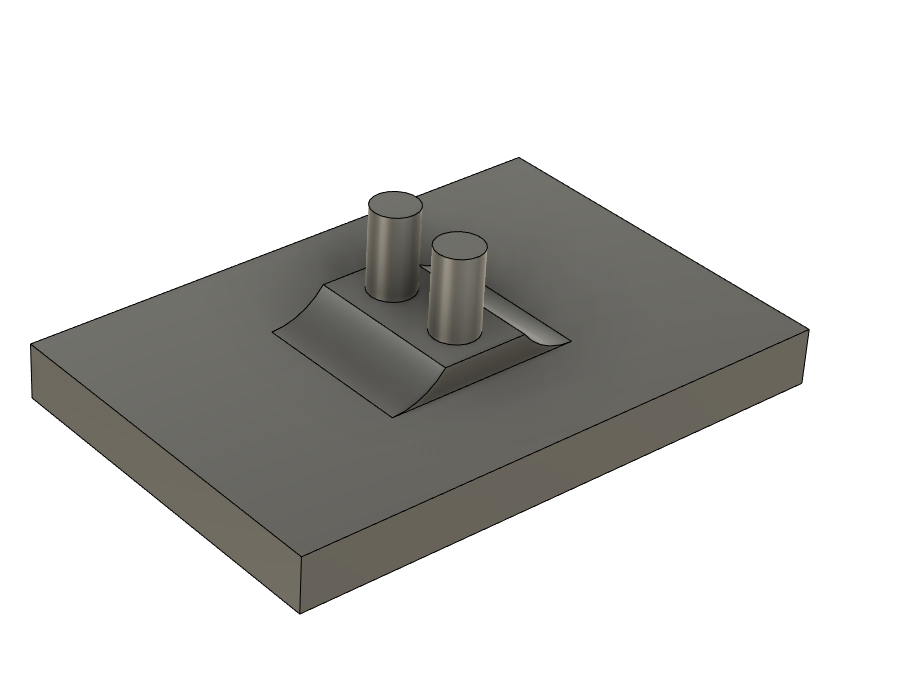
With in a few days of obtaining the load cell I did my best to measure it with a caliper so I could design a mounting base and a load plate. It took me 4 tries to get the diameter of the two “pins” associated with the top plate to fit snugly.
The 4 “Top” Versions shown in the picture are all printed in PETG plastic. I manually measured the pins to be approximately be 2.65 mm, 2.91mm, 3.08mm for V1 through V3. The final “Top” was designed to have 0.1mm greater diameter than V3, but I have had a difficult time measuring this with my calipers.
You can also see that V1 was designed to sit higher than the other versions. The gap between the plates and the Load cell was designed to be 2mm from the metal and ~1mm from the silica gel.
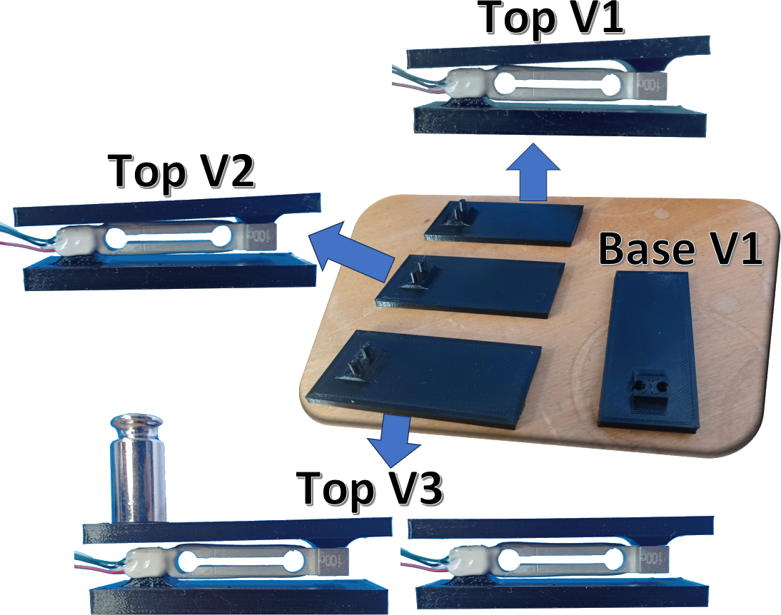
I believe my first pin design gave a 0.3mm total diameter reduction from the through hole measurement I initially made. That proved to be too loose, therefore, I remeasured the hole and tried a value close to what I measured for the load cell. In the end, I designed the pin size of the “TOP” scale to be 3.3mm in diameter. This was 0.1mm greater than the through hole measurement I made of 3.2mm.
The base plate V1 exposed the edge of the screw sticking through it because I was concerned that the silica gel was overlapping more than it actually was, and I wanted to make sure it did not get squished in-between the load cell and the base.

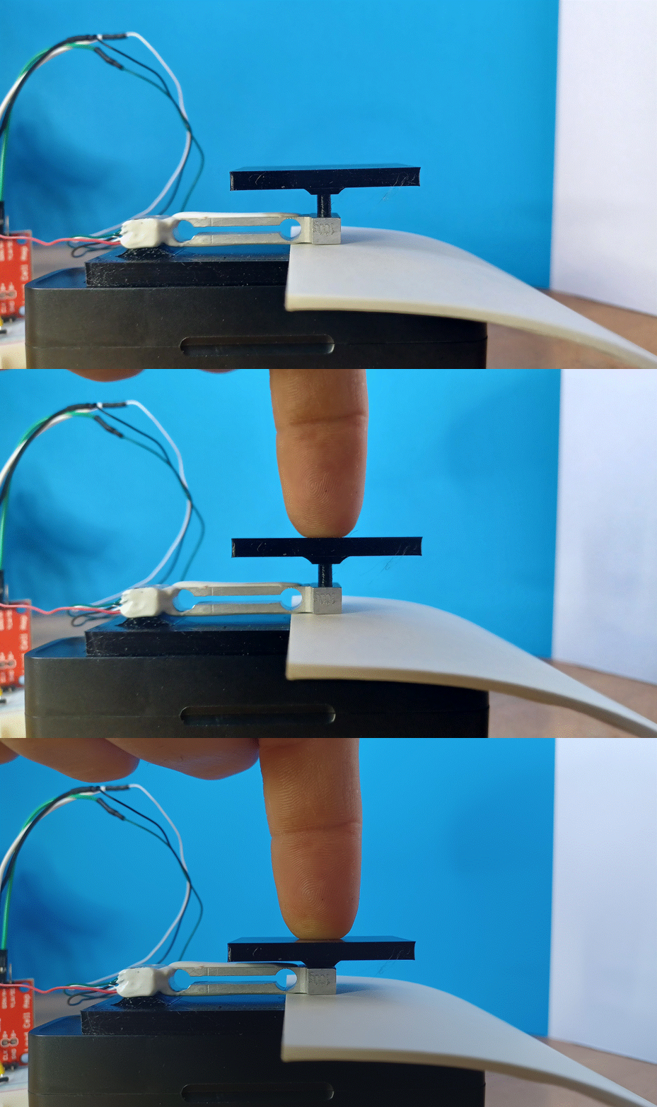
When assembling the final top piece I used a stack of papers, to make sure I did not over-stress the load cell. I am not sure if this is possible, but I did this just in case.
The next step in the process required me to solder headers onto the load cell amplifier (HX711). Since I still feel very basic in my soldering skills, I watched the video located on this page (https://learn.adafruit.com/adafruit-guide-excellent-soldering/tools) to get some quick and useful pointers. I soldered the small wires with the help of a QuadHands tool. I used some heat shrink to clean it up and prevent shorting the wires.
To read the digital signal coming from the load cell amplifier, I used an Arduino nano rp2040 connect. This specific hardware is not required of course, but I plan to use this or something similar in the future because I like its small size, large amount of memory and many remote connection abilities.
Finally, I wired it as pictured:
GND to GND
CLK to Pin 4 (digital pin)
DAT to Pin 2 (digital pin)
VCC to 5V
VDD to 3.3V
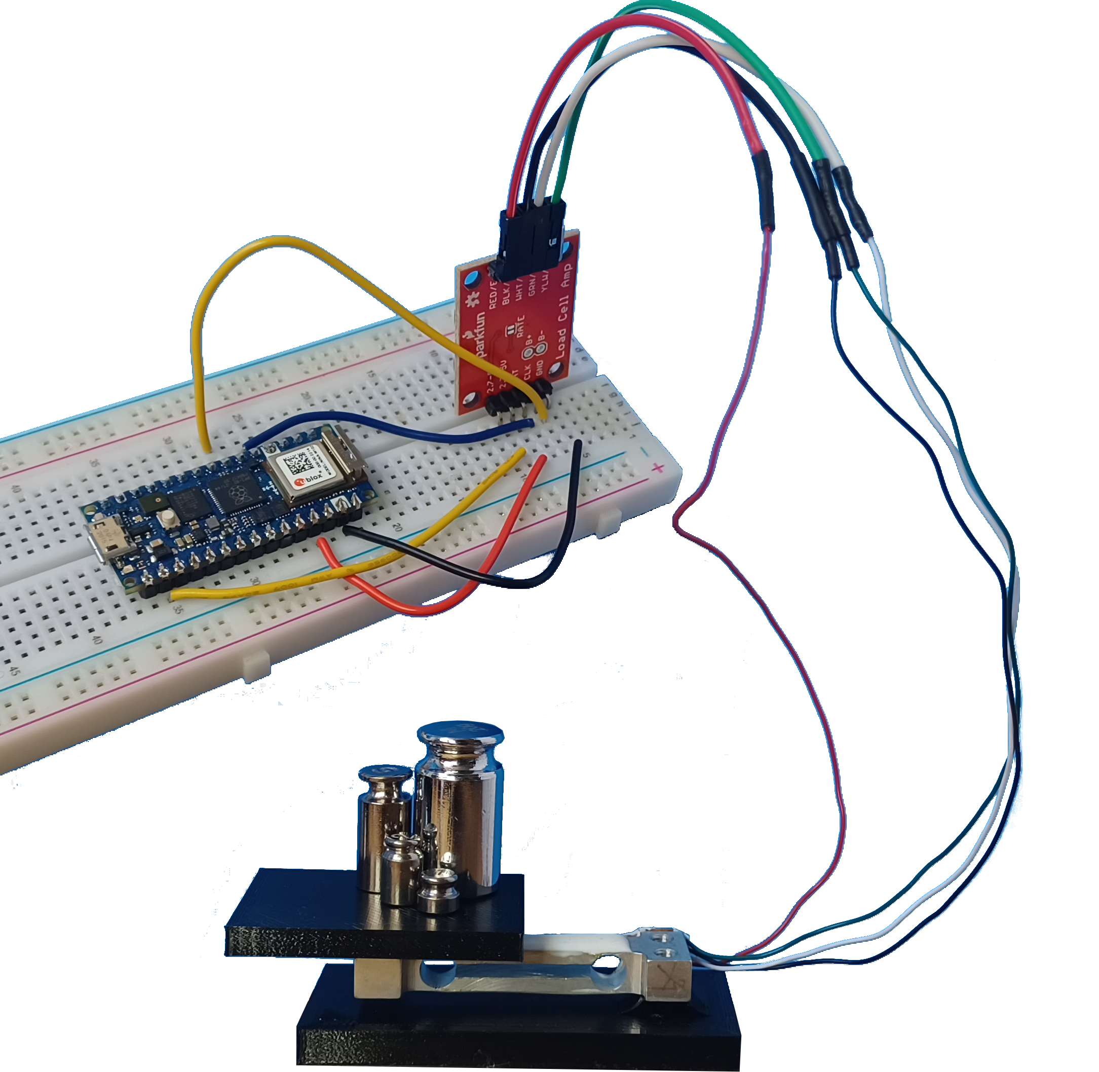
I chose the VCC and VDD based on a “Pro Tip” found on https://learn.sparkfun.com/tutorials/load-cell-amplifier-hx711-breakout-hookup-guide?
I did not take the time to figure out why, I just wanted to see if I could get this working.
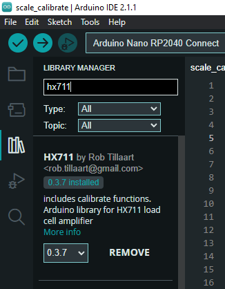
Finally, for the code I used what was written by Rob Tillaart (https://github.com/RobTillaart/HX711).
I chose this by looking at the github webpage and noticing that it had the most recent edits and seemed like it might have good examples.
I used the Library Manager as shown in the Arduino IDE software version 2.1.1.
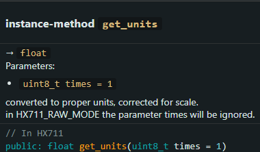
I was initially confused by the language used for his function called “get_units”. I thought this meant the get the units being used for the measurement.
But, from using the function and the mouse-over description it looks like this is the function is used to get the calibrated weight.
The input value to this function is named “times” and I think means the the number of measurements to average. To be sure of this I would need to dig into his library which I have yet to do.
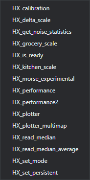
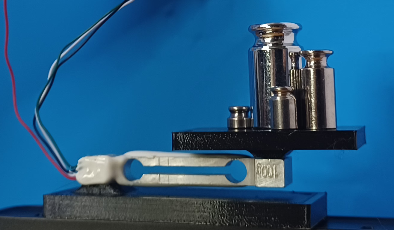
I calibrated with a 20g weight, using his HX_calibaration example with a minor edit, of changing the pins for CLK and DAT.
I just had to make sure that I set the Serial connection rate to 115200 baud rather than the default of 9600 baud.
The calibration gave me an offset and scale value that I plugged into the test code shown below.
Calibration code used
					//
//    FILE: HX_calibration.ino
//  AUTHOR: Rob Tillaart
// PURPOSE: HX711 demo
//     URL: https://github.com/RobTillaart/HX711

#include "HX711.h"

HX711 myScale;

uint8_t dataPin = 2;
uint8_t clockPin = 4;

uint32_t start, stop;
volatile float f;

void setup()
{
  Serial.begin(115200);
  Serial.println(__FILE__);
  Serial.print("LIBRARY VERSION: ");
  Serial.println(HX711_LIB_VERSION);
  Serial.println();

  myScale.begin(dataPin, clockPin);
}

void loop()
{
  calibrate();
}

void calibrate()
{
  Serial.println("\n\nCALIBRATION\n===========");
  Serial.println("remove all weight from the loadcell");
  //  flush Serial input
  while (Serial.available()) Serial.read();

  Serial.println("and press enter\n");
  while (Serial.available() == 0);

  Serial.println("Determine zero weight offset");
  myScale.tare(20);  // average 20 measurements.
  uint32_t offset = myScale.get_offset();

  Serial.print("OFFSET: ");
  Serial.println(offset);
  Serial.println();

  Serial.println("place a weight on the loadcell");
  //  flush Serial input
  while (Serial.available()) Serial.read();

  Serial.println("enter the weight in (whole) grams and press enter");
  uint32_t weight = 0;
  while (Serial.peek() != '\n')
  {
    if (Serial.available())
    {
      char ch = Serial.read();
      if (isdigit(ch))
      {
        weight *= 10;
        weight = weight + (ch - '0');
      }
    }
  }
  Serial.print("WEIGHT: ");
  Serial.println(weight);
  myScale.calibrate_scale(weight, 20);
  float scale = myScale.get_scale();

  Serial.print("SCALE:  ");
  Serial.println(scale, 6);

  Serial.print("\nuse scale.set_offset(");
  Serial.print(offset);
  Serial.print("); and scale.set_scale(");
  Serial.print(scale, 6);
  Serial.print(");\n");
  Serial.println("in the setup of your project");
  Serial.println("\n\n");
}
//  -- END OF FILE --
Test Code used
As can be seen in the test code below, the offset used for my setup was 4294568309, and the scale was -17464.005859.
The code just starts outputting the scale value with a delay between outputs of 0.25 seconds. It seemed slower than 4 data points a second when I tested it, but I was just happy to see that I was actually getting the correct values for the weights that I put on the scale.
Also, I do not think either code block shown here waits for the user to connect over the serial port… this is annoying… but I do not plan to use this exact code in the future, so I am going to leave it as is for this log entry.
					#include "HX711.h"

HX711 myScale;

uint8_t dataPin = 2;
uint8_t clockPin = 4;

uint32_t offset = 4294568309;
float scale = -17464.005859;

void setup() {
  // put your setup code here, to run once:
  Serial.begin(115200);//Set data rate in bits per sec (baud)
  while(!Serial);
  Serial.println(__FILE__);
  Serial.print("LIBRARY VERSION: ");
  Serial.println(HX711_LIB_VERSION);
  Serial.println();

  myScale.begin(dataPin, clockPin);
  myScale.set_offset(offset);
  myScale.set_scale(scale);
}

void loop() {
  // put your main code here, to run repeatedly:
  Serial.println(myScale.get_units(10));
  delay(250);
}
The code written defines the dataPin and clockPin using unsigned 8 bit integers, which you can tell by the type definition of uint8_t. From my previous arduino coding, I had not seen this type definition from their reference webpage. Apparently cross platform type definitions are marked with an _t according to the C99 standard for C++. Therefore, I think it would be best practice to use these definitions. Not too long ago I did run into an issue where I believe I used an int definition that ran differently on an Arduino Mega 2560 (ATmega2560 microcontroller), vs the Nano RP2040 (RP2040 microcontroller).
Possible learning exercises for the future:
- Look at the plugin functions, so I can understand the actual communication with the Hx711.
- Probe the communication pins with an oscilloscope (DAT & CLK)
Lists of useful webpages
